Decoding Quinetic In-Line Relays and Switch Relays, and bridging them to MQTT and Home Assistant
17th November 2025
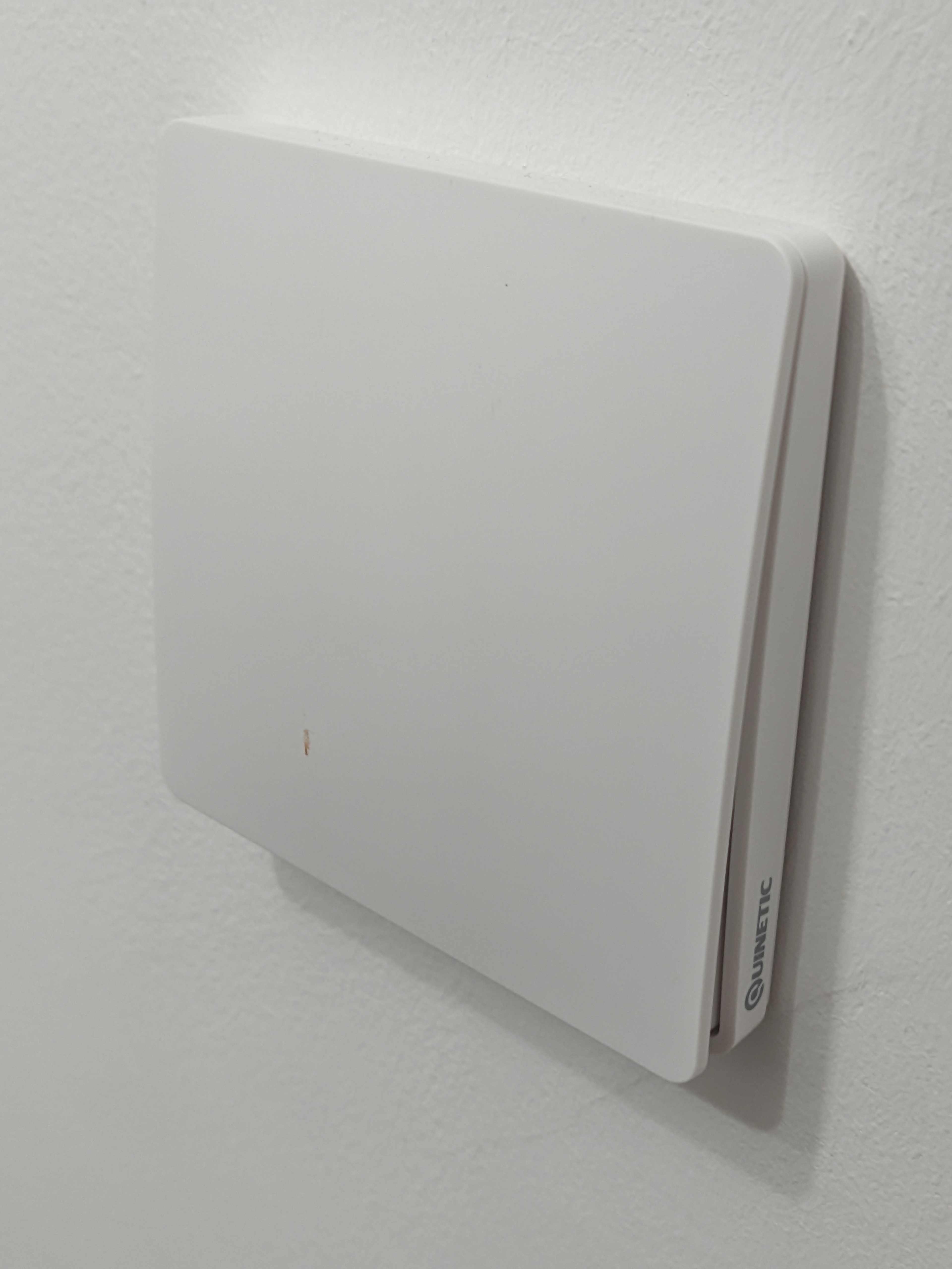
Recently I outfitted my flat with a bunch of Quinetic branded switches and switch relays. These are some really neat bits of kit that can really easily wirelessly control lights without a lot of malarkey. The walls in my flat are concrete so running new wires is exceptionally disruptive, but there were a couple areas where having a light switch on all the entrances to a room were really helpful. These switches filled that gap, and the switches themselves are self powered from the force of you pushing them which is truly excellent for my terminal ADHD brain, no batteries to replace or things to charge (it also let me caulk the switches in place so they looked really neat). An option you can add is their hub, which allows you to control their branded relays and in line switch relays (which go in the place of normal light switches and act as both receivers for the switch only units as well as normal light switches) from an app on your phone, but naturally for any piece of smart home equipment the app is completely unusable buggy garbage and I have no idea what this mystery hub is getting up to on my network, so I want to supercede it with Home Assistant. A bit of research showed a couple people had already worked on this a bit. Cameron Gray wrote a bit of arduino code that reads the signals from the switches and translates them to MQTT messages which can go into Home Assistant. It seems to have been based off this work by Secfault Security, where they reverse engineered the protocol with an SDR. However none of this work has targeted the relays and in line switches. Whilst I absolutely could chuck all the relays and switch relays, and replace the lot with a combo of the switch only units and third party relays (the shelly relays look very nice, and I might be using them on other bits of this home automation setup), that would make the lighting dependent on the Home Assistant server staying online, and I'm not a fan of that. If the cpu in my server pops or the wifi craps out that would leave me unable to use the main lighting, which to me is unacceptable. These little things are perfectly happy talking to each other to turn lights on and off and I do not want to compromise that at all. The automation should be additional, not a requirement. Thus I set myself the goal of figuring out how the heck these units work and what needs to be done to get them interfaced to MQTT
Hardware
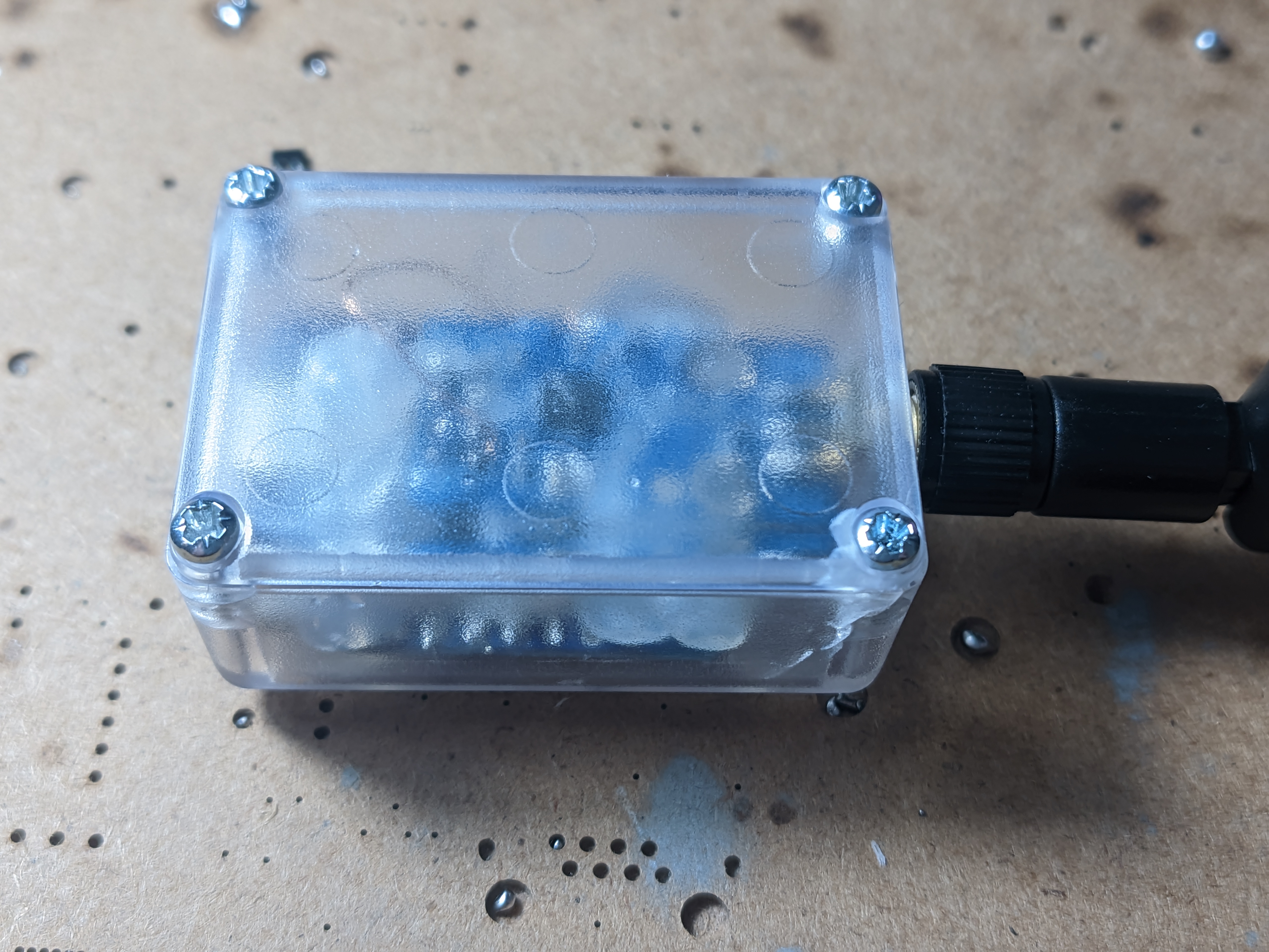
Given all these bits talk to each other it's a safe bet the modulation scheme and important radio message components e.g. preamble and sync word are identical, so an identical hardware setup to Cameron's work can be used. I ordered the cheapest CC1101 module and a D1 mini ESP8266 board with USB-C (I considered trying to port it to ESP32 but I didn't want to get caught up in any issues doing so, so stuck to the 8266). I also picked up a little project box to stick it in, as at the end of this project I'm gonna need to get this little contraption plugged into power somewhere so it can do it's job. I wired the module into the radio (a task made harder than it should be by the complete absence of pinout information on the radio PCB or the eBay listing I got it from, I had to use the pinout from an identical looking item on AliExpress and pray), melted some corresponding holes in the project box for the usb c connector and antenna and proceeded to overconfidently glue the boards in place with copious amounts of hot glue. In hindsight this was a terrible mistake as I downloaded the code, installed the libraries and hit flash just to watch it dismally fail. esptool.py would give a "Timed out waiting for packet header" error and no matter what I tried it wouldn't work. Some rudimentary googling indicated I may have shot myself in the foot again by getting the cheapest ESP8266 I could find. Apparently clone D1 mini boards have an under rated voltage regulator that often craps out under the load of flashing the board, and it's even worse with something attached to the 3.3v rail. Fortunately the pinout was common to the voltage regulators I had in the drawer, so I replaced it with a slightly less under rated XC6219 and it flashed fine, then it wouldn't initialise the radio. I'd managed to completely screw up the pinout on the SPI wires to the radio, and had to remove the whole thing (god bless IPA for loosening hot glue) and resolder it. One more hiccup and replacement of the voltage regulator again after accidentally shorting it and it could receive packets from the switch I was testing on my desk just fine. Really the lesson heree is twofold. Don't buy the absolute cheapest parts on eBay and don't overconfidently seal the case up when you're not sure if it's going to work at all. An additional lesson is a clear housing isn't the best idea if you're going to hot glue everything in as it really doesn't look good, but I couldn't care less given this'll be shoved in some corner.
Initial testing
When I fired up Cameron's code (after disabling all the MQTT bits) I kept getting "Error: Invalid CRC" messages in the serial log, which made my spidey senses tingle, as it's unlikely that everything is failing to calculate the CRC, and it's much more likely that the messages don't follow the expected format for the switches alone. I started by disabling the CRC check and printing the raw messages and a lot more information was coming through now, and things such as me turning the in line switches on and off would show clear changes, but nothing in the message matched the CRC, and I dodn't expect them to use a different CRC protocol or anything like that, so I guessed these used a larger packet size. Turning the packet size up to 10 gave much more promising results, with 8 bytes of data and the CRC16 at the end of the message (Discovering the existence of the crccalc.com website was very nice). The final assistive tool was adding the RSSI to the serial strings so I could tell if the messages were coming out the hub with its antenna directly next to my receiver, or from the switches dotted around the place. A couple more basic principle things could now be quickly discerned, the systems seem to operate in a poll response loop, where the hub polls all known units every minute or so, and they all respond with their current state. Each unit also sends a message when its state changes when someone presses its built in switch or a switch paired to it, and when the hub sends out a command the addressed unit responds pretty quickly. A lot of the message didn't seem to change as time or things changed, it was only a couple bytes in the poll and response cycles, so it's probably pretty simple. This initial information gives a pretty good idea of what needs to be added to support these things. The receiver needs to have it's own pairing mechanism where it can collect a list of known IDs that it can poll and command; whilst I've not got any experience with Home Assistant I'm assuming once I get round to that bit this list of IDs can be imported and dealt with there, one problem at a time! This will be simpler than the original scheme I had in mind, where the receiver would have the ability to fake being a couple different switch IDs and could command downstream devices that way.
Full decoding
I got a couple minutes of messages, along with me spamming the commands in their crap app on all the units in my flat, then dropped it in a spreadsheet and started decoding. If there's one thing my new job has made me good at it's Excel, so I was able to pretty formulaically dismantle the messages and figure out if they're coming from the hub or the device. The cliffnotes are as such (please note this is only for the single channel units, as that's all I've got). The first four bytes are the device IDs (On the relay switches and relays they're printed on a sticker on the device, for some unknown reason they are not the same as the one on the sticker on their smart plugs, but tbh their smart plugs are crap and I don't recommend using them). The next four bytes are the fun ones. The hub will send 0x0D, 0x00, 0x55 0xAA to poll the device, the device will respond with 0x0D, 0x01, 0x07, then 0x00 if it's off and 0x01 if it's on. The control seems different between the relay switches and plain relays/smart plugs. For the switches the hub sends 0x0B, 0x01, 0x07, then 0x00 to switch it off and 0x01 to switch it on. When the device changes state (from a hub initiated state change) the device sends 0x0C, 0x01, 0x07, then 0x00 if off 0x01 if on. For the plugs and relays the hub sends 0x0B, 0x01, 0x02, then 0x00 or 0x01 and they respond 0x0C, 0x01, 0x01, then 0x00 or 0x01. When the devices change state from external input they send 0xA5, 0x01, 0x01 or 0x07, then 0x00 or 0x01. My guess is the middle two bytes are for other channels on multi channel devices, or perhaps the dimmer channel or RGB controller Quinetic offer. Decoding these bytes is left as an exercise to the reader. The final two bytes of the message are the CRC16, it's the same CRC16-AUGCCITT that the switches alone use.
Transmitting experiments
I started by fairly cluelessly just jamming a transmit hardcoded 10 byte packet into my modified version of camerons code, and to absolutely nobodys surprise, it didn't work at all in any way. Once I actually read through the code (probably should have started with this tbh) I realised the code only uses the tail 2 bytes of the 3 byte sync word, because the CC1101 only supports a two byte sync word in the automatic detection register. I tried setting the sync word to the first two bytes and adding the final byte in the message but that didn't work either. A more detailed reading of the original secfault reverse engineering revealed the issue. For some reason the kinetic switches insert an extra 0 bit in between the preamble and the sync word. What I did was put this bit into the sync word. Shifting the sync word right by one bit leads to an initial 2 byte sync word of 0x10, 0xD2. Then you need to prepend 9 bits onto your message, 000100011. I ended up building this all into a little sender program so I could experiment without breaking the main receiver code and it didnt work at first. This was because the kinetic switches use a 40 bit preamble, and the code was originally using a 16 bit preamble. The CC1101 doesn't support a 40 bit preamble but conveniently a 32 bit one works just fine, and that got everything working properly for one sending, but the board had to be reset in between transmissions. I was able to make it work by manually flushing the TX FIFO but that is a really bodgy solution. It turned out I had been looking at outdated example code. The latest examples for RadioLib had a couple changes to whatever random version I'd been looking at before. I had to wire an additional pin from the GDO2 connection on the radio module to D2/GPIO4 on the ESP (Not to D4 or D0 and those are strapping/not interrupt capable pins and cause all sorts of havoc, as I learnt the hard way), and made some light code tweaks to use the new pin and properly configure the interrupt enabled transmission mode of RadioLib. Next I needed to get the sending a bit better than just hardcoded byte strings. This was done with an eye to full integration later on, so I rewrote the function that I wrote to shift and prepend the message to construct the message as well, taking a uint32 device id, a message state enum with the three different types of switching device messages that travel across the airwaves and the set state. Because of the funkiness where the relays and relay switches having different message constructions a few bits of tinkering with the C conditional operator were required, then the correct CRC gets smacked on the end of the message and it's ready for sending. I gave this a bit of testing and it all seemed to be working well, so the next steps were to get simultaneous transmitting and receiving working.

Simultaneous transmit and receive
For simultaneous transmit and receive I started with my test transmitting code, added in the interrupt driven receive bits from the original Kinetic2MQTT code and let it rip and as per usual immediately ran into issues. The GDO2/packet sent interrupt would keep triggering despite my best attempts to make it not do that. I traced this issue back to a bug in the library when the interrupts are configured. The same event is used for both the transmit complete and receive complete flags, but there's no enabling and disabling of them to properly manage the states. After adding some additional flags to my code so the ISRs would only do something in their appropriate Tx/Rx states multiple transmissions would still not go through. After a lot of faffing around trying various dodgy tricks I had the bright idea to enable debug logging, at which point it naturally started working perfectly... When something like that crops up it's very often a delay thing, which lined up with the timeout error I was getting. It seems the CC1101 doesn't seem to like switching back and forth between tx and Rx modes, and it needs a little longer to let the clock stabilise when you do so rapidly, increasing the timeout delay from 800us to 1500us got all my transmissions working an absolute treat, and I could move on to some basic structural stuff, like refactoring out the message construction and parsing into a header file I could drag between the various versions of the code. I reported the two library bugs I found to the maintainer and they addressed them within just a couple days, which was very nice.
IotWebConf setup
IotWebConf is a pretty powerful library for entering configuration data on a captive portal, and then having that data be stored on the device. I was originally thinking of doing a dedicated pairing mechanic, but entering the device IDs into IotWebConf is significantly easier to program. This does mean all the device IDs need to be entered manually which kind of sucks, especially if (like me) you've caulked and painted these switches into your walls so I threw together a quick receiver sketch that periodically prints device IDs it sees, the idea being you can flash this onto your reciever, run around hitting all the switches and relays (in the same way the quinetic hub tells you to to pair new devices) and it'll print a nice list of ids for you in comma separated format for Excel wrangling. It also has two debug modes where it prints its decoded messages, also in comma separated, and raw messages if you're reverse engineering a new Quinetic device. Creating the new web form wasn't too bad, it could be automatically populated with device ids through a little for loop. With the list of device IDs each device can be periodically polled, but given the polling isn't really necessary I added a define to disable it, although on connection it always polls all the known devices so Home Assistant gets the correct state. One thing I had to be a bit careful with was delays, because there's only the one radio I can't send a whole load of messages out simultaneously if I also want to listen for inputs, so when polling on start I added a delay of 250ms between each poll so it can listen for the response from each one. The state of every device it detects gets tracked, so the switch debouncing still works properly.
MQTT
Before this project I'd never had the oportunity to experiment with MQTT, but I know people raved about it as a way to have a whole load of WiFi connected devices talking to each other, and a lot of home automation stuff relies on it. One of the many apps available for TrueNAS SCALE is Eclipse Mosquitto, which seems to be a very popular MQTT server (although I think the technical term is broker). One thing rather poorly documented about the Mosquitto app is it doesn't really work properly out of the box, you have to either enable anonymous mode to allow unauthenticated connections, or add users and passwords. I followed this Reddit comment and that worked an absolute treat, although note you have to add ACLs to the data and config paths to allow user 568 to have modify access which wasn't massively well explained. I also installed MQTTX so I could send messages from my desktop, and begun experimenting. I created another test script that used the IotWebConf library to connect to my WiFi network and the MQTT broker, and I could send and see messages on the serial console. The final message structure I setup was as follows: There's a root topic called "kinetic", with three sub topics, system (where the device reports its connected), state (where the state and polling reports from downstream devices get published), and set (where Home Assistant sends the set commands). The state and set topics have a topic a level down that's the ID of the switch. Messages are JSON formatted, with state, message type, device type, and RSSI being sent in the device report and messages to the device having a state 1 to turn the device on and a 0 to turn it off. To do the JSON formatting I used the ArduinoJSON library, which is probably not the most efficient way of doing things, but it did the job. After some experimentation with the PubSubClient examples and tying them into IotWebConf I wrote some code to connect everything together and was successfully able to send MQTT messages from my desktop to turn my lights on and off.
Home Assistant integration
After installing the TrueNAS SCALE Home Assistant app (Note you need to check the "automatic permissions" box when configuring host paths for the postgres data store), I stepped through the Home Assistant setup steps and started fiddling with integrations. The first step was installing the MQTT integration and configuring the broker settings as I set them up on mosquitto (The TrueNAS Home Assistant app doesn't seem to resolve mDNS requests so I needed to pipe the full IP into it, this is pretty common for TrueNAS apps). Once that was done I could experiment using the Home Assistant MQTT light integration. There were a couple different ways to approach the issue. The hardest to configure but the easiest to repeat would be MQTT discovery, which seems to be a way for MQTT devices to announce themselves and their communication standards to Home Assistant, I didn't end up going that route because it looked like it would add a really tricky job to the firmware. The first thing I tried was a basic "default" schema, which was relatively quick and easy to get control working through the "payload_on" and "payload_off" settings, but no matter what I tried the state would never properly update, it would always read as "unknown". This turned out to be because home Assistant expected devices to say their state is "ON" or "OFF" rather than 1 or 0, but because the switches report funky values changing the firmware to support that wasn't really feasible, so what I did instead was write a "template" schema which had some if statements using the Home Assistant implementation of Jinja2 and that got the state updating properly when it was changed through Home Assistant, but not when I was manually changing switches. This turned out to be me missing one of the state messages, which got sent using a different byte. I was kind of hoping I could template the setup somehow so I could instantiate multiple copies of it without copying everything, but I couldn't figure out how to do that, so I had to do it all manually, but I got it all set up and it works a treat. Now it's time for a whole load more fun home Assistant things!
Source and further links
The source code and a basic README for this project can be found here. If people take this concept and develop it some more I'd love to see PRs with improved features